Technical Specifications
Warranty Information
All the products supplied by Evelta are genuine and original. We offer 14 days replacement warranty in case of manufacturing defects. For more details, please visit our cancellation and returns page.
All the products supplied by Evelta are genuine and original. We offer 14 days replacement warranty in case of manufacturing defects. For more details, please visit our cancellation and returns page.
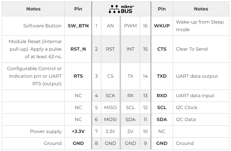
The MIKROE-2545 RN4678 Click Board integrates the RN4678 Bluetooth 4.2 dual mode module from Microchip. It is designed to run on a 3.3V power supply. It communicates with the target microcontroller over I2C and UART interface, with additional functionality provided by the following pins on the mikroBUS line: AN, RST, CS, PWM, INT.

| Designator | Name | Default Position | Default Option | Description |
| JP1 | P2_0 | Left | HIGH | System configuration pin - Along with P2_4 and EAN pins, used to set the module in any of the following three modes: Application mode (for normal operation), Test mode (to change EEPROM values), and Write Flash mode (to enter the new firmware into the module) |
| JP2 | P2_4 | Left | HIGH | System configuration pin - Along with P2_0 and EAN pins, used to set the module in any of the following three modes: Application mode (for normal operation), Test mode (to change EEPROM values), and Write Flash mode (to enter new firmware into the module) |
| JP3 | EAN | Right | LOW | External address-bus negative pin. System configuration pin along with P2_0 and P2_4 pins, used to set the module in any of the following three modes: Application mode (for normal operation), Test mode (to change EEPROM values), and Write Flash mode (to enter new firmware into the module); |