The LIS3DH Breakout operates on 3.3V and 5V both supplies. This sensor communicates over I2C or SPI both interfaces. The LIS3DH is an ultra-low-power high-performance three-axis linear accelerometer belonging to the “nano” family, with digital I2C/SPI serial interface standard output. The device features ultra-low-power operational modes that allow advanced power saving and smart embedded functions. The LIS3DH has dynamically user-selectable full scales of ±2g/±4g/±8g/±16g and is capable of measuring accelerations with output data rates from 1 Hz to 5.3 kHz.
Board Features- +-2g/+-4g/+-8g/+-16g dynamically selectable full scale
- I2C/SPI digital output interface
- 16-bit data output
- 2 independent programmable interrupt generators for free-fall and motion detection
- 6D/4D orientation detection
- Free-fall detection
- Motion detection
- Embedded temperature sensor
- Dimensions : 25 x 23 mm
1 x Arduino UNO R3 Clone4 x 1 Pin Jumper Wire (Male) - Pack of 101 x Breadboard - 830 Holes 54mm x 166mm
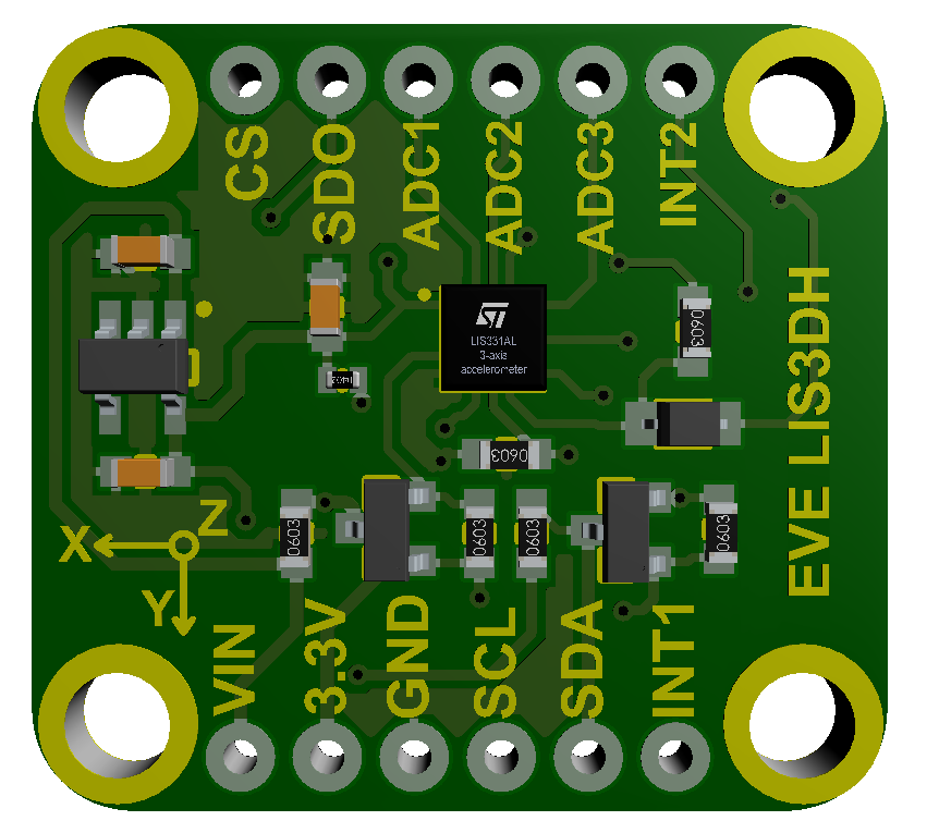 Breakout Board Pin FunctionVin - this is the power pin. Since the chip uses 3 VDC, we have included a voltage regulator on board that will take 3-5VDC and safely convert it down. To power the board, give it the same power as the logic level of your microcontroller - e.g. for a 5V micro like Arduino, use 5V 3.3V - this is the 3.3V output from the voltage regulator. GND - common ground for power and logic SCL - I2C clock pin, connect to your microcontroller's I2C clock line. SDA - I2C data pin, connect to your microcontrollers I2C data line. This is the Serial Data In / Microcontroller Out Sensor In pin, for data sent from your processor to the LIS3DH To use I2C, keep the CS pin either disconnected or tied to a high (3-5V) logic level. SDO - When in I2C mode, this pin can be used for address selection. This is the Serial Data Out / Microcontroller In Sensor Out pin, for data sent from the LIS3DH to your processor. CS - this is the Chip Select pin, drop it low to start an SPI transaction. It's an input to the chip. INT1 - is the interrupt output pin. You can configure the interrupt to trigger for various 'reasons' such as motion, tilt, taps, data ready etc. INT2 - is the second interrupt output pin. You can configure the interrupt to trigger for various 'reasons' such as motion, tilt, taps, data ready etc.
ADC1 - ADC3 - Analog to Digital converter inputs 1-3.
LIS3DH Arduino I2C Connection

Using the Arduino Library ManagerThe library manager was added starting with Arduino IDE versions 1.5 and greater (1.8.x). It is found in the 'Sketch' menu under 'Include Library', 'Manage Libraries...'
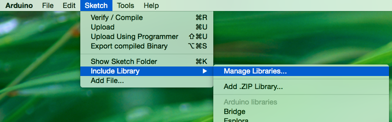
Arduino 1.5+ Library Manager Menu Option
When you open the Library Manager you will find a large list of libraries ready for one-click install. To find a library for your product, search for the product name or a keyword such as 'k type' or 'digitizer', and the library you want should show up. Click on the desired library, and the 'Install' button will appear. Click that button, and the library should install automatically. When installation finishes, close the Library Manager.

Alternatively, if you have a library of your own you would like to add or a library that hasn't been added to the Library Manger yet, you can click the 'Add .ZIP Library' option, which will then allow you to choose a folder or *.zip file containing the library of your choice.
Now that the library is installed, an example sketch can be found in the 'Examples' submenu.
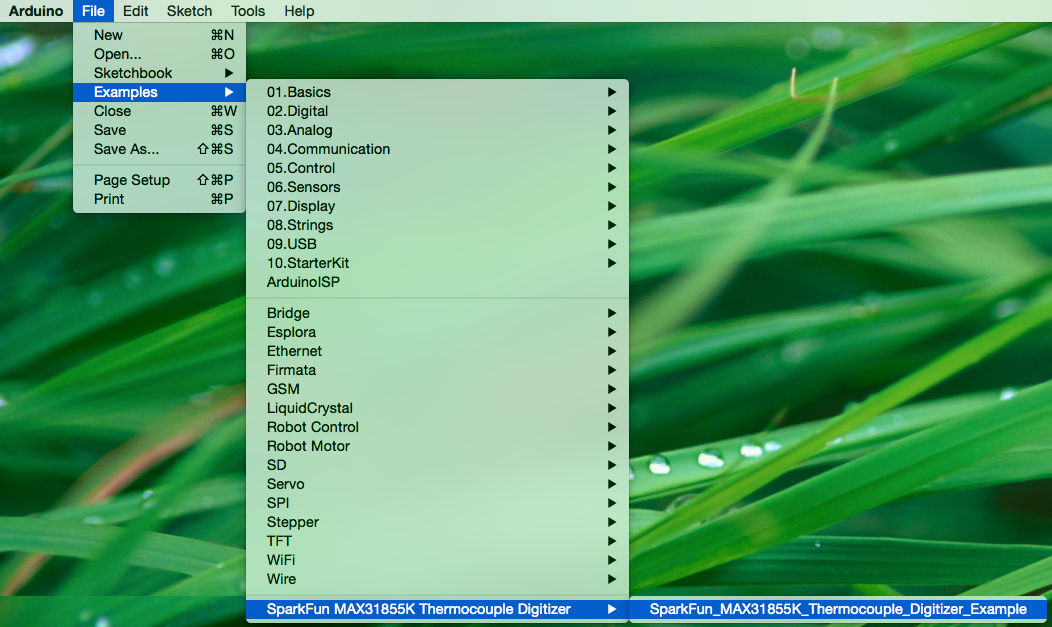
Example Sketch
Test the Arduino CodeStart with just the basic accelerometer sketch, also called "MinimalistExample" from the library. This will periodically sample the sensor and display data as the number of Gs detected. Remember, the vertical axis will read 1G while sitting at rest. #include "SparkFunLIS3DH.h"#include "Wire.h"
#include "SPI.h"
LIS3DH myIMU; //Default constructor is I2C, addr 0x19.
voidsetup() {
// put your setup code here, to run once:
Serial.begin(9600);
delay(1000); //relax...
Serial.println("Processor came out of reset.\n");
//Call .begin() to configure the IMU
myIMU.begin();
}
voidloop()
{
//Get all parameters
Serial.print("\nAccelerometer:\n");
Serial.print(" X = ");
Serial.println(myIMU.readFloatAccelX(), 4);
Serial.print(" Y = ");
Serial.println(myIMU.readFloatAccelY(), 4);
Serial.print(" Z = ");
Serial.println(myIMU.readFloatAccelZ(), 4);
delay(1000);
} Output
