UART Protocol Explained: From Basics to Advanced Implementation
Published by Vineet Gupta on 13th Sep 2025
UART (Universal Asynchronous Receiver-Transmitter) ranks among the oldest computer communication devices, with its roots in connecting teletypewriters to computers. The first single-chip UART (the WD1402A) emerged in 1971, and this protocol remains the life-blood of digital communication in modern electronics. UART communication achieves an impressive 80% protocol efficiency through its standard configuration of 8-data bits, no parity, and 1 stop bit.
UART communication protocol serves as an economical solution for device-to-device interaction, particularly in embedded systems and microcontrollers. Its easy-to-use interface makes implementation straightforward in applications of all types. UART's asynchronous operation allows devices with different clock rates to communicate without sharing a clock signal. The protocol plays a crucial role in automotive diagnostics, consumer electronics, industrial automation, and healthcare devices. Its significance grows even more in the expanding Internet of Things (IoT) ecosystem. This piece walks you through UART communication basics, frame format structures, internal operations, and advanced implementation techniques to help you become skilled at using this versatile protocol.
Understanding UART Communication Protocol
Electronic devices interact through serial communication protocols. These protocols are the foundations of data exchange between microcontrollers, sensors, and hardware components. UART has become one of the most accessible protocols because it takes a straightforward approach to data transmission.
Definition of UART and its asynchronous nature
UART (Universal Asynchronous Receiver-Transmitter) is a hardware communication protocol. It lets devices transfer data asynchronously with adjustable speed and format settings. UART works without a shared clock signal to coordinate data transmission, unlike synchronous communication protocols. The transmitting and receiving UARTs must agree on communication parameters beforehand. The baud rate becomes especially important as it sets the speed of data bits traveling across the line.
"Asynchronous" means devices sync their timing without using a dedicated clock line. A UART changes parallel data from a CPU or microcontroller into serial form. It sends this data bit by bit to another UART that converts it back to parallel data. Both the sending and receiving UARTs use shift registers for this conversion process.
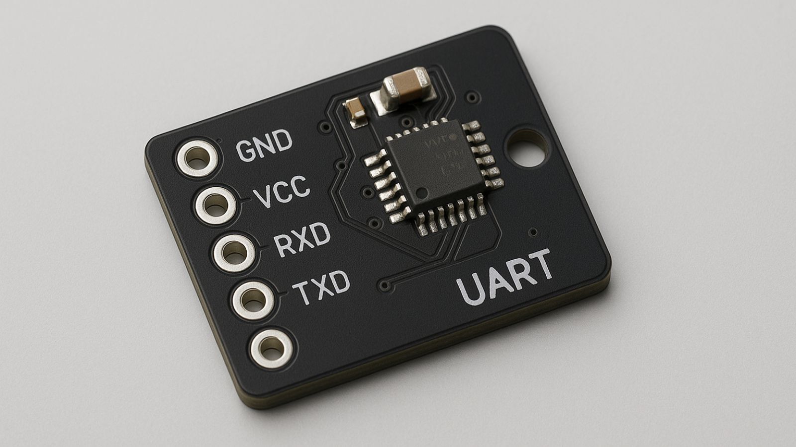
You need just two wires for UART communication: a transmit (TX) wire and a receive (RX) wire, with signals linked to a common ground. One device's transmitter connects to another's receiver in what we call a null modem setup. This simple wiring makes UART perfect for systems that need minimal circuit complexity.
Comparison with synchronous protocols like SPI and I2C
UART is different from synchronous protocols like SPI (Serial Peripheral Interface) and I2C (Inter-Integrated Circuit) in several ways:
-
Clock Synchronization: UART uses start and stop bits in each data frame for syncing, while SPI and I2C need dedicated clock signals.
-
Wiring Complexity: UART needs only two wires for two-way communication. SPI typically needs four lines, and I2C uses two lines but needs extra addressing.
-
Data Rates: UART runs at lower speeds, usually between 9,600 and 115,200 bits per second. SPI can reach much higher speeds (10-20 Mbps), making it better for high-throughput needs.
-
Implementation Simplicity: UART is easier to set up and needs less configuration than SPI and I2C's complex sync mechanisms.
UART remains valuable for slower-speed and lower-throughput tasks because it's simple, economical, and easy to implement, even though faster protocols have replaced it in many high-speed applications.
Common use cases in embedded systems
Embedded systems use UART in many ways:
Engineers often use UART for debugging and development. It helps them log system outputs and catch diagnostic messages when they find system bugs early. This feature is a great way to get insights while fixing complex embedded systems.
UART also combines smoothly with various wireless modules, including Bluetooth, Zigbee, and GPS devices. Many wireless communication modules use UART as their main interface, making it crucial for IoT and connected device applications.
Manufacturing teams use UART's detailed logging features to track production line activities. UART also helps with software updates and testing processes that check product quality before shipping.
Cars use UART for diagnostic communication. Modern computers often use USB-to-UART bridges to work with older serial devices. UART supports both one-way (simplex) and two-way simultaneous (full-duplex) data transmission, which makes it flexible enough for various applications.
UART Frame Format and Data Transmission
UART communication works best with well-laid-out data frames as its foundation. Data moves between devices in packets. Each packet has specific parts that make sure devices can exchange data reliably. You need to understand these frame elements to make UART work in your projects.
Start bit, data bits, parity, and stop bits
UART devices stay in an idle state with both transmit (TX) and receive (RX) lines at logic high voltage when not sending data. The sending device starts transmission by pulling the TX line from high to low for one clock cycle - this creates a start bit. The receiving device notices this voltage change and knows data is coming, so it starts reading bits at the preset baud rate.
The actual data bits come right after the start bit. UART can handle 5-9 data bits, but most devices use 7 or 8 bits. These bits carry the real information like ASCII characters or numbers. The least significant bit always goes first in UART transmission. The letter 'S' in 7-bit ASCII (binary 1010011) would flip to 1100101 before sending.
A parity bit might come next to catch errors. The frame ends with one or two stop bits that push the transmission line back to high state. These stop bits tell the receiver the frame is done and get both devices ready for more data.
8N1 configuration and protocol efficiency
8N1 stands out as one of the most used UART setups. The "8" means eight data bits, "N" shows there's no parity bit, and "1" tells us there's one stop bit. This setup strikes a good balance between quick data transmission and catching errors.
Each byte needs 10 bits to transmit with 8N1 (1 start bit + 8 data bits + 0 parity bits + 1 stop bit). The protocol runs at 80% efficiency - that's 8 useful bits out of every 10 sent. Ethernet might hit 95% with big frames, but UART keeps steady efficiency no matter the message size. Small messages on Ethernet are nowhere near as efficient because of minimum payload rules.
Your best bet for faster data transfer is to bump up the baud rate instead of changing the frame format. To name just one example, sending a 41-byte message 50 times per second with 8N1 needs: 41 bytes × 10 bits per frame × 50 Hz = 20,500 bits per second. You'd need at least 20,500 baud to avoid jamming the communication line.
Error detection using parity bit
Parity bits offer a quick way to spot transmission errors. They work by keeping track of logic high bits (1s) in the data frame - either an even or odd count. Even parity means the total number of 1s (including the parity bit) should be even. Odd parity makes sure the total stays odd.
Take the number 55 (binary 00110111). This binary number has five 1s (odd count). Even parity would add a 1 to make the total even. Odd parity would add 0 to keep the total odd.
The receiver knows something's wrong if a single bit flips during transmission. The number 167 (binary 10100111) with even parity would raise an alert if the fourth bit got corrupted - the receiver would see an odd count instead of even. Bad data gets tossed out, and the system might ask for a resend.
Parity checks have their limits though. They only catch odd-numbered bit errors. Two flipped bits would slip through unnoticed. On top of that, it just finds errors - it can't fix them.
Internal Components and Operation of UART
UART interfaces rely on sophisticated hardware components that work together to transmit data reliably. Learning about these components helps us understand how UART protocols work at the hardware level.
Role of shift registers and FIFO buffers
Shift registers are the backbone of UART communication. They convert data between parallel and serial formats. The transmitting shift register takes parallel data from the system and outputs it one bit at a time. A receiving shift register collects incoming serial bits and builds them into complete bytes. This conversion lets microcontrollers process data in parallel while they communicate serially with external devices.
Modern UARTs use First-In-First-Out (FIFO) buffers that improve communication performance by a lot. Early UARTs like the 8250 or 16450 had just a 1-byte buffer. This meant systems had to process each byte right away to avoid data loss. Advanced UARTs like the 16550A come with 16-byte FIFOs. These allow multiple characters to be processed with a single interrupt and reduce CPU overhead. Some newer UART designs have even larger buffers—up to 128 bytes—which streamline processes in high-throughput applications.
Clock synchronization in receiver
UART receivers use sophisticated clock synchronization techniques, even though they're asynchronous. The receiver's internal clock runs 16 times faster than the baud rate to sample incoming bits accurately. The receiver detects the start bit's falling edge and waits half a bit time. It then samples each following bit at its midpoint. This oversampling helps extract reliable values from each bit period and handles slight timing variations well.
Transmitter operation and busy flag handling
Transmitter operation follows a simple process. Data written to the transmit register goes into the transmit FIFO before being sent out serially. The UART sets a "busy" flag during transmission to protect current data from being overwritten. This flag stays active until all bits—including the stop bit—have been sent and the FIFO becomes empty.
Advanced UARTs let you configure FIFO trigger levels. These create interrupts when the buffer reaches specific thresholds—usually 1/8, 1/4, 1/2, 3/4, or 7/8 of capacity. Timeouts ensure that partially filled receive buffers get processed. Most UARTs wait about four character times before triggering a timeout interrupt.
Advanced UART Implementation Techniques
Advanced UART techniques improve communication reliability, security, and efficiency in complex systems. Simple UART functionality works for many applications, but sophisticated features become essential when developing reliable communication protocols for critical applications.
Custom frame protocol with headers, trailers, and CRC
Custom frame protocols add vital security layers to UART communication by ensuring devices exchange data with intended partners. A custom protocol needs both transmitting and receiving devices to use similar configurations. This approach reduces connection errors and unauthorized access. A well-laid-out frame has unique identifiers such as Header 1 (H1) and Header 2 (H2)—to name just one example, 0xAB and 0xCD respectively. These headers work as signatures that authenticate the communicating device.
The protocol structure has command selection fields, data length indicators that vary based on the selected command, and the actual payload data. The frame ends with distinctive trailers (such as T1: 0xE1 and T2: 0xE2). CRC implementation provides critical error detection capabilities that identify accidental data alterations during transmission.
Baud rate calculation using UART_DIV and UART_FBR
Accurate baud rate calculation remains fundamental for reliable UART communication. The baud rate divisor (BAUDDIV) follows this formula: BAUDDIV = (F_UARTCLK / (16 × Baud rate)). This divisor has an integer value (BAUD_DIVINT) stored in UARTIBRD and a fractional value (BAUD_DIVFRAC) stored in UARTFBRD.
Non-integer divisors need accurate fractional part calculations: m = integer((fractional_part × 64) + 0.5). A 4MHz clock and 230400 baud rate results in BAUDDIV equals 1.085, giving BRDI = 1 and BRDF = 0.085, which converts to a fractional value of 5. This method achieves a generated baud rate of 231911, with an error of only 0.656%.
Flow control: hardware vs software methods
Flow control prevents data loss when connecting devices with different processing speeds. Hardware flow control, also called RTS/CTS flow control, uses additional signal lines. The nUARTRTS signal stays asserted until the receive FIFO reaches its programmed watermark level with RTS flow control enabled. The transmitter sends data only when nUARTCTS is asserted with CTS enabled.
Software flow control works without additional wires and uses special characters (typically XON/XOFF, ASCII 0x11/0x13) transmitted through normal data lines. This budget-friendly approach provides simplicity but increases CPU overhead and potential latency. Hardware flow control delivers better reliability, automatic management, and lower latency. This makes it ideal for high-speed communications despite needing additional wiring.
UART Models and Real-World Applications
UART technology has evolved by a lot over decades. Different models now meet the needs of modern electronic systems. Each UART model comes with unique features that address specific communication requirements in various applications.
16550 UART with FIFO buffer
The 16550 UART marks a breakthrough in serial communication technology. This innovation introduced FIFO (First-In, First-Out) buffers. Early UARTs like the 8250 or 16450 had just a 1-byte buffer. Systems had to issue interrupts for each byte of data received. The 16550A changed this with its 16-byte FIFO. This improvement means systems can process multiple characters with a single interrupt, which reduces system overhead. The 16550A lets you choose from four receive trigger levels (RTL): 1, 4, 8, and 14 bytes. This flexibility helps you match your application's needs. The 16550 works in two modes: standard UART mode and FIFO mode. FIFO mode turns on internal buffers to boost performance.
USB-to-UART bridges for modern PCs
Modern computers no longer come with traditional serial ports. USB-to-UART bridges stepped in as the solution to keep UART-based devices working. These bridges act like translators between interfaces. They take data from one side and send it through the other. The MSP430F5529 microcontroller shows how well this works. It handles both USB and UART communication at 24MHz clock speed and 9600 baud rate. Popular options like the CP210x USB-to-UART bridge need special Virtual COM Port (VCP) drivers to talk to the host. These bridges use FIFO buffers to handle speed differences between USB and UART protocols. This smart design prevents data loss.
Use cases in automotive, IoT, and industrial systems
UART interfaces show their value in many industries:
-
Automotive Applications: UART connects microcontrollers, sensors, and entertainment systems in vehicles. Mechanics use it to read fault codes from onboard computers.
-
IoT Implementations: Wireless communication modules like Zigbee, LoRa, and Bluetooth use UART to talk to microcontrollers. GPS modules send location data through UART interfaces.
-
Industrial Systems: Manufacturing plants use UART to connect central controllers with industrial components. This enables up-to-the-minute monitoring and control. Human-Machine Interfaces (HMI) often use UART to link microcontrollers with display units or touchscreens.
Conclusion
UART technology dates back to the early 1970s and remains the life-blood of modern electronic communications thanks to its remarkable versatility and simplicity. This piece shows how this asynchronous protocol transmits data efficiently with minimal wiring needs compared to SPI and I2C alternatives. The protocol's 80% efficiency with standard 8N1 configuration are the foundations of countless applications in a variety of industries.
UART's internal architecture showcases elegant engineering that balances simplicity with effectiveness through its shift registers and FIFO buffers. These components enable smooth parallel-to-serial conversion and manage timing differences between communicating devices. Advanced UARTs with larger buffers cut down CPU overhead by a lot. This makes them perfect for high-throughput applications without risking reliability.
On top of that, error detection mechanisms like parity checking offer essential protection against transmission errors in many applications, despite their simplicity. UART communication becomes more robust and secure when paired with custom frame protocols and CRC implementation. The system's flexibility to calculate precise baud rates using divisors and fractional components will give compatibility between devices running at different clock frequencies.
UART without doubt holds strong in automotive diagnostics, IoT infrastructure, and industrial automation systems, even as newer communication protocols emerge. USB-to-UART bridges have extended the protocol's lifespan by connecting legacy serial devices with modern computing systems. Embedded systems designers value UART because it's straightforward to implement and performs reliably.
Note that becoming skilled at UART implementation builds a solid foundation for more complex communication protocols. Your skills in understanding frame structures and implementing flow control mechanisms will prove valuable in projects of all sizes. UART has evolved since its early days, but its core principles stay unchanged, powering countless devices in our increasingly connected world.
FAQs
Q. What is UART and how does it differ from other communication protocols?
A. UART (Universal Asynchronous Receiver-Transmitter) is an asynchronous serial communication protocol that operates without a shared clock signal. Unlike synchronous protocols like SPI and I2C, UART requires only two wires for bidirectional communication and is simpler to implement, making it ideal for lower-speed applications.
Q. What is the typical frame format used in UART communication?
A. A typical UART frame consists of a start bit, 5-9 data bits (commonly 8), an optional parity bit, and 1-2 stop bits. The most common configuration is 8N1, which means 8 data bits, no parity, and 1 stop bit, resulting in a protocol efficiency of 80%.
Q. How does UART handle error detection?
A. UART can use parity bits for basic error detection. Even or odd parity ensures that the total number of 1s in the data frame (including the parity bit) is even or odd, respectively. This method can detect single-bit errors but cannot correct them or detect multiple-bit errors.
Q. What are FIFO buffers in UART and why are they important?
A. FIFO (First-In-First-Out) buffers in UART are memory structures that store multiple bytes of data. They significantly enhance communication performance by allowing multiple characters to be processed with a single interrupt, reducing CPU overhead and improving efficiency in high-throughput applications.
Q. How is UART used in modern applications?
A. UART is widely used in various fields including automotive diagnostics, IoT devices, and industrial systems. It facilitates communication between microcontrollers, sensors, and wireless modules. In modern computers, USB-to-UART bridges maintain compatibility with legacy serial devices, extending UART's utility in contemporary electronics.