How to Setup RS232 to 485 Converter: Quick Guide for Industrial Networks
Published by Alok Jain on 11th May 2025
An RS232 to 485 converter can transform your industrial communication capabilities. It extends the range from 15 feet to a remarkable 4000 feet (1200 meters). RS485 networks have become the top choice for industrial applications that need long-range, reliable communication.
These converters deliver data transmission rates up to 115,200 BPS, which keeps your industrial network running at peak efficiency. The RS485 to RS232 converter gives you the flexibility to connect multiple devices through RS232 RS485 interfaces or build a network with up to 32 RS485 devices in a point-to-multipoint setup. These devices are tough enough for harsh industrial environments and come with 15KV static protection and 600W surge protection. The RS232 to 485 converter pinout and proper RS232 to 485 converter schematic are vital elements for a successful implementation.
This piece will show you how to set up and configure your RS232 to RS485 converter for the best performance. You'll discover everything from simple communication principles to detailed connection instructions. The result is a strong industrial communication network that works across long distances while keeping your data secure.
Table of Contents:
- Understanding RS232 to RS485 Communication Basics
- Key Hardware Components and Pinout Reference
- Power and Protection Requirements for Industrial Use
- Step-by-Step Setup Guide for RS232 to 485 Converter
- Troubleshooting Common RS232 to RS485 Issues
- Conclusion
- FAQs
Understanding RS232 to RS485 Communication Basics
RS232 to RS485 converters are vital bridges between two fundamentally different communication standards. These protocols work quite differently - RS232 is a single-ended interface that works up to 15 meters (50 feet) and picks up noise easily. RS485 takes a different approach with balanced differential signaling. This makes it immune to common-mode noise and lets it work at distances up to 1200 meters (4000 feet).
Half-Duplex vs Full-Duplex in RS485
Data flow direction in your communication system is what we call "duplex". Half-duplex RS485 setups use one twisted pair of wires where data travels both ways - just not at the same time. You'll see this setup more in industrial settings because it needs fewer wires but still handles multi-point networks well.
Full-duplex RS485 needs four wires (two twisted pairs) and lets you send and receive data at the same time. This setup makes RS485 work much like RS422, with continuous two-way communication. Your choice between these modes comes down to what you need:
-
Half-duplex (2-wire): Less expensive wiring, easier to install, but no simultaneous send and receive
-
Full-duplex (4-wire): Allows two-way communication at once, better throughput, but needs more complex wiring
Why RS485 is Preferred in Industrial Networks
Industrial settings create special challenges that RS485 handles really well. RS485 can connect 32 devices on one network without repeaters, or up to 256 devices with them. This multi-drop feature cuts down wiring complexity compared to point-to-point RS232 connections.
RS485's differential signaling gives it excellent noise immunity - this is a big deal as it means that motors, welding equipment, and other electrical noise sources won't interfere. RS485 handles data rates up to 10 Mbps over short distances. The rule of thumb says your speed (bits/second) times cable length (meters) should stay under 10^8.
RS485 works great with standard automation protocols. Many industrial control systems use it as the physical layer for Modbus RTU and Profibus. RS485 networks also support linear bus topologies that work well in factory settings.
Common Use Cases for RS232 to RS485 Converters
These converters work in all types of industries where longer communication distances or multiple device connections matter. Industrial automation uses them to help PLCs talk to remote sensors, motor drives, and other equipment. Control centers can monitor and adjust variable frequency drives (VFDs) from far away.
Building automation is another big use case. RS485 networks control lighting, HVAC systems, and security equipment in large buildings. Yes, it is especially useful in surveillance systems that connect security cameras and access control readers to central monitoring stations.
The sort of thing I love about these converters is how they're used in performance venues for DMX512 protocol to control lighting systems. Transportation applications include vehicle bus networks in commercial aircraft cabins where reducing wire weight matters.
Modern converters come with auto-direction functions that make manual flow control unnecessary. They switch between transmit and receive modes on their own, which ensures reliable data exchange even in complex industrial networks.
Key Hardware Components and Pinout Reference
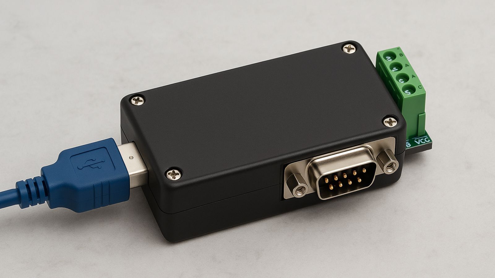
A proper understanding of hardware components and their connectivity leads to successful implementation of an RS232 to 485 converter. These converters change single-ended RS232 signals into balanced differential RS485 signals. This change allows data transmission up to 1200 meters instead of just 15 meters with RS232. Physical connections and configuration options are vital parts of reliable industrial communication networks. Let's get into the components and their pinout references for proper setup.
RS232 to 485 Converter Pinout Explained
Standard interface connectors with specific pinout configurations are common in RS232 to 485 converters. These devices usually come with a female DB9 connector on the RS232 side and either a male DB9 connector or terminal blocks on the RS485 side. The converter's design includes several key components: the RS232 driver/receiver chip, RS485 transceiver, and isolation circuits for industrial environments.
The RS232 side needs three basic connections: Transmit Data (TXD), Receive Data (RXD), and Signal Ground (GND). Data+ (B) and Data- (A) terminals handle communication on the RS485 side, along with a ground reference. Industrial-grade converters often include jumpers for network termination and failsafe biasing during bus idling.
Modern converters feature auto-direction functionality. This feature uses auto-direction detection through a monostable flip-flop that triggers by the start bit from the RS232 receiver instead of Request-to-Send (RTS) signals. The auto-direction approach gives better results than RTS-based switching, especially in Windows environments where timing can be unpredictable.
DB9 Connector Mapping for RS232
The RS232's DB9 connector has nine pins that handle specific serial communication functions. You'll need to know this pinout to connect your converter correctly:
|
Pin |
Signal |
Description |
Direction (DTE) |
|---|---|---|---|
|
1 |
DCD |
Data Carrier Detect |
Input |
|
2 |
RXD |
Receive Data |
Input |
|
3 |
TXD |
Transmit Data |
Output |
|
4 |
DTR |
Data Terminal Ready |
Output |
|
5 |
GND |
Signal Ground |
- |
|
6 |
DSR |
Data Set Ready |
Input |
|
7 |
RTS |
Request to Send |
Output |
|
8 |
CTS |
Clear to Send |
Input |
|
9 |
RI |
Ring Indicator |
Input |
Basic asynchronous communication needs only pins 2 (RXD), 3 (TXD), and 5 (GND). All the same, some converters utilize other pins like RTS (pin 7) for direction control or DTR (pin 4) to help with power supply when the converter draws power from the RS232 port.
Computer serial COM ports usually have male DB9 connectors while peripheral devices use female ones. This standard setup prevents wrong connections and arranges signal directions properly between Data Terminal Equipment (DTE) like computers and Data Communication Equipment (DCE) like modems or converters.
2-Wire vs 4-Wire RS485 Configurations
The difference between 2-wire (half-duplex) and 4-wire (full-duplex) RS485 configurations shapes network design choices. A 2-wire setup uses one twisted pair for both transmission and reception in one direction at a time. The 4-wire configurations allow simultaneous bidirectional communication through separate twisted pairs.
The 2-wire RS485 connections need jumper wires to connect transmission and reception pins on the RS485 port. You must connect TXD+ to RXD+ and TXD- to RXD-. This setup connects the 2-wire device's transmit pin (TXD) to both TXD- and RXD- on the converter, while the receive pin (RXD) connects to both TXD+ and RXD+.
The 4-wire setup keeps separate paths for transmission and reception, which enables full-duplex communication like RS422. This configuration requires careful master-slave relationship setup, as the master's transmitter connects to the slave's receiver and vice versa.
A daisy-chain topology works better than star, T-drop, or ring arrangements that can cause signal reflections at high speeds. Termination resistors (usually 120Ω) at both network ends minimize reflections and maintain signal integrity. Shielded twisted-pair cables boost immunity from electromagnetic interference in industrial settings.
Power and Protection Requirements for Industrial Use
You need to think about power requirements and protection features when choosing the right RS232 to 485 converter for industrial applications. Industrial networks work in tough environments. Temperature extremes, electrical noise, and voltage changes can threaten communication quality. Power options and protection specs become just as important as knowing the right pinout setup.
Port-Powered vs External Power Supply
Industrial RS232 to 485 converters come with two power options: port-powered operation or external power supply. Port-powered converters pull current straight from RS232 data lines and use a capacitor charge pump to create the needed voltage. This setup needs no external power cables, which makes installation simpler. However, port power might not be enough, especially when you have signal mismatches or low voltage from the host device.
Externally powered converters work reliably whatever the RS232 port's power level. These units work with different input voltages, from 5V DC terminal connections to wider ranges like 9V-240V based on the model. Mission-critical industrial setups benefit from externally powered units with isolation. They stop ground loops and protect equipment from electrical damage.
600W Surge Protection and 15KV Static Shielding
Industrial-grade RS232 to RS485 converters have strong protection against electrical hazards. The standard protection has 600W surge protection plus 15KV electric static discharge (ESD) protection. These features guard expensive equipment from voltage spikes, lightning effects, and other electrical problems common in factories.
Advanced models use optical isolators that split data lines inside the unit. This creates complete electrical barriers between equipment. The isolation stops damage from ground loops and adds extra protection for valuable network equipment.
Operating Temperature and Humidity Ranges
Industrial environments push equipment to extremes that would break standard commercial devices. So industrial-grade RS232 to 485 converters work in temperatures from -40°F to 185°F (-40°C to 85°C)[172]. You can use them anywhere from freezing outdoor spots to hot factory floors.
These devices handle humidity from 5% to 95% non-condensing. This is nowhere near what commercial-grade equipment can handle. Your industrial communication setup lasts longer and works better even in challenging conditions.
Step-by-Step Setup Guide for RS232 to 485 Converter
Setting up an RS232 to 485 converter needs precise connection details and proper configuration to work reliably in industrial environments. You can establish strong data links across extended distances with the right setup. Here's a straightforward guide to set up your industrial network.
Connecting RS232 to RS485 Terminals
The RS232 to 485 converter setup starts with proper wiring on both sides. Connect the DB9 female connector to your computer or control device with a standard RS232 cable on the RS232 side. The RS485 side features a terminal block that provides screw-lug wire terminations to make field connections easier.
For a simple point-to-point setup:
-
Connect the RS485 converter's Data A(-) line to the slave device's A(-) terminal
-
Connect the RS485 converter's Data B(+) line to the slave device's B(+) terminal
-
Connect the ground wire between both devices to create a steady reference point
Multi-drop networks need consistent polarity throughout. Make sure A(-) connects to A(-) and B(+) connects to B(+) across all nodes in a daisy-chain configuration.
Termination Resistor Placement
Termination resistors play a vital role in minimizing signal reflections in your RS485 network. These resistors should match your cabling's characteristic impedance—usually 120Ω for standard twisted-pair cables.
To terminate properly:
-
Add termination resistors only at both far ends of the bus network
-
Half-duplex (2-wire) configurations need termination resistors at both extreme cable ends, not on middle devices
-
Full-duplex (4-wire) setups require termination resistors on receiver sides of both the master device and the furthest slave device
Short distances or low communication speeds don't need termination. Distances under 1,000 feet with baud rates below 115 kbit/s work fine without termination, which would only draw more power.
Testing Communication with Modbus RTU
The physical connections lead to testing your setup with Modbus RTU protocol. Your devices need matching serial communication parameters:
-
Connect a USB-to-RS485 adapter between your PC and RS485 device
-
Set similar communication parameters (baud rate, data bits, parity, stop bits)
-
Open a Modbus polling software like Modbus Poll
-
Configure the serial port settings and select RTU mode
-
Set the slave address, function code, and register addresses
Your display should show request and response messages during monitoring. A working test displays transmitted and received data. Request messages look like "0a 03 00 00 00 02 c5 70" with responses like "0a 03 04 01 43 01 29 70 95". Failed communication needs connection verification, parameter checks, and ground loop inspection.
Troubleshooting Common RS232 to RS485 Issues
A quick identification of the root cause saves valuable time if your RS232 to RS485 network fails. Signal issues, parameter mismatches, and electrical interference cause most communication problems. You can solve these problems with a systematic approach.
No Signal on RS485 Line
Incorrect wiring polarity or termination problems usually cause signal absence on an RS485 line. You should verify that A(-) and B(+) connections keep consistent polarity throughout your network. Many failures happen because one device's polarity gets reversed. The B line should read more positive than the A line when you check idle network voltage with a voltmeter. A connection problem exists if this isn't the case. Biasing resistors prevent transient voltages from being misinterpreted as network traffic. RS485 transceivers might fail to detect valid idle states without proper biasing.
Incorrect Baud Rate or Parity Settings
Mismatched communication parameters lead to most RS232 to RS485 communication failures. Both devices must have similar baud rate, data bits, parity, and stop bits to work. Many devices come with a default baud rate of 115,200 bits per second, though some equipment runs slower. Set all devices to match the same parameters to troubleshoot—usually 8 data bits, no parity, and 1 stop bit (8N1). Some devices in Modbus RTU environments just need two stop bits with no parity. This often creates confusion.
Ground Loop and Isolation Problems
Proper grounding is crucial to work. RS485's "2-wire interface" actually needs 3 wires—A, B, and signal ground. Data corruption occurs without this reference connection when ground potential differences exceed the transceiver's common-mode range. Ground loops create serious problems in installations across multiple buildings or power sources. These loops create unwanted current paths that add noise and might damage equipment. Galvanic isolation through optical isolators or 100-ohm resistors in series between signal ground connections solve these problems.
Conclusion
RS232 to 485 converters play a vital role in building resilient industrial communication networks. This piece shows how these devices revolutionize basic 15-foot RS232 connections into powerful networks that span up to 4000 feet while data integrity stays intact. RS485's differential signaling mechanism definitely offers better noise immunity than single-ended RS232 interfaces. This makes it perfect for tough industrial environments where electrical interference can disrupt communication reliability.
You can design networks that balance performance with practical implementation costs by knowing the key differences between half-duplex and full-duplex configurations. A stable communication system needs proper termination resistor placement, careful polarity monitoring, and the right grounding techniques. These technical aspects might look daunting at first, but a systematic approach makes them manageable.
Quality converters with industrial-grade protection features shield your equipment from environmental electrical hazards. The 600W surge protection and 15KV static shielding will give you peace of mind. Your investment in quality converters with proper protection ratings pays off through improved system reliability and longer life. These devices work consistently in temperatures from -40°C to 85°C, whatever the deployment conditions.
The most important part is that you now have practical ways to fix common issues like signal absence, parameter mismatches, and ground loops. This knowledge helps you spot and fix communication problems quickly, which reduces downtime in critical industrial applications. RS232 to 485 conversion technology stays relevant today because it's simple, reliable, and economical compared to newer methods.
Successful industrial automation needs both advanced control systems and solid communication infrastructure. The simple RS232 to 485 converter forms a crucial part of this infrastructure. It enables everything from basic sensor monitoring to complex multi-device control networks across long distances. Your time spent learning about these converters will without doubt lead to more reliable and efficient industrial communication systems.
FAQs
Q. How do I connect an RS232 to RS485 converter?
A. Connect the RS232 side to your computer or control device using a standard RS232 cable. On the RS485 side, connect the Data A(-) line to the slave device's A(-) terminal, the Data B(+) line to the B(+) terminal, and establish a ground connection between devices.
Q. What are the advantages of using RS485 in industrial networks?
A. RS485 offers superior noise immunity, longer transmission distances (up to 4000 feet), and the ability to connect multiple devices on a single network. It's also compatible with common industrial protocols and supports higher data rates in noisy environments.
Q. How do I troubleshoot communication issues with my RS232 to RS485 converter?
A. Check for correct wiring polarity, verify that all devices have matching communication parameters (baud rate, data bits, parity, stop bits), and ensure proper grounding. Also, inspect for potential ground loops and consider using optical isolators for enhanced reliability.
Q. Do I need termination resistors in my RS485 network?
A. Termination resistors (typically 120Ω) should be placed at both far ends of the RS485 bus to minimize signal reflections. However, they may not be necessary for short distances (under 1,000 feet) or low communication speeds (below 115 kbit/s).
Q. What protection features should I look for in an industrial-grade RS232 to RS485 converter?
A. Look for converters with 600W surge protection and 15KV static shielding to guard against electrical disturbances. Additionally, consider models with extended temperature ratings (-40°C to 85°C) and high humidity tolerance for harsh industrial environments.