Current Sensor Types Explained: Which One Fits Your Application
Published by Alok Jain on 30th Aug 2025
Current sensors are vital parts of the electronic devices you use every day. They work behind the scenes in your smartphone's battery management and your electric vehicle's power control system. The ability to measure electrical current with precision can make all the difference between a system that runs perfectly and one that fails.
Different current sensing technologies serve different purposes. Simple shunt resistors and sophisticated Hall effect sensors each have their own strengths. The right sensor choice depends on several factors. You need to review the measurement range, response time, and isolation requirements. These elements match up with your application's specific needs to help you make the right choice.
This piece gets into various current sensing technologies and shows you how they work in real applications. You'll discover each sensor's operation principles, performance metrics, and which options work best for your project.
Table of Contents:
- Understanding the Basics of Current Sensing
- Types of Current Sensors and Their Core Principles
- Materials and Methods: Building a Current Sensor Circuit
- Performance Metrics and Real-World Benchmarks
- Results and Discussion: Matching Sensors to Applications
- Limitations and Trade-Offs in Sensor Selection
- Conclusion
- FAQs
Understanding the Basics of Current Sensing
Current sensing works on two basic physical principles: voltage drop and magnetic field interaction. These principles are the foundations of all current sensor types we have today. We can measure voltage directly, but electrical current needs indirect measurement methods that depend on measuring the effects of current flow in a circuit.
Ohm's Law and Voltage Drop in Current Measurement
Ohm's Law is the life-blood of electrical engineering that shows the mathematical relationship between voltage, current, and resistance. This basic law states that voltage (V) equals current (I) multiplied by resistance (R): V = I × R. You need one volt of pressure to push one amp of current through one ohm of resistance. This relationship is what makes resistive current sensing technologies work.
The shunt resistor method is the most common way to sense current. This method puts a resistor with a known value in series with the current path. Current flowing through this resistor creates a voltage drop based on Ohm's Law. The voltage drop matches the current flowing through the circuit, which gives us a measurable signal showing the current's size.
In spite of that, shunt-based sensing has one major challenge: the voltage drop across the resistor is usually tiny, especially with low-resistance shunts that minimize power loss. This small voltage signal needs amplification for accurate measurement. Engineers use precision operational amplifiers (op-amps) to boost the voltage while keeping measurement accuracy.
Several important factors come into play when choosing shunt resistors for current sensing:
-
Resistance value: Lower resistance cuts power loss but reduces measurement sensitivity
-
Power rating: Must handle I²R power dissipation without overheating
-
Temperature coefficient: Affects measurement stability across temperature changes
-
Parasitic inductance: Can affect high-frequency current measurement accuracy
Shunt-based current sensors have clear benefits like low cost, high measurement accuracy, and knowing how to measure both AC and DC currents across a wide range. The downside is that this approach adds resistance to the circuit path, which can create unwanted loading effects and generate power loss according to P = I²R.
Magnetic Field Interaction in Current Sensor Working Principle
The second basic principle used in current sensing involves the magnetic field that current creates when flowing through a conductor. Maxwell's Equations of Electromagnetism tell us that any current-carrying conductor makes a magnetic field that matches the size of the current flowing through it. This principle lets us measure current without contact, which solves some problems that resistive sensing has.
Hall effect sensors are a leading technology based on this principle. These sensors detect voltage induced perpendicular to current flow when exposed to a magnetic field. Edwin Hall found this effect in 1879, which works on the physical principle of the Lorentz force. Current flowing through a conductor creates a magnetic field, and a Hall effect sensor near the conductor produces a voltage that matches the field strength, showing the current's size.
Other magnetic field-based current sensors include:
-
Rogowski coils: Air-core coils wrapped around a conductor that create voltage matching current change rate, perfect for measuring AC currents and quick events
-
Current transformers: Use electromagnetic induction to change high currents into measurable low currents
-
Magnetoresistive sensors: Use materials whose electrical resistance changes with magnetic field strength
Magnetic field-based current sensing works better than resistive techniques in many ways. These sensors provide electrical isolation between the sensing circuit and measured current path, which makes them safer and reduces interference. They work without touching the current-carrying conductor, which eliminates power losses you get with shunt resistors. These sensors can also measure currents from milliamperes to thousands of amperes.
The biggest challenges for magnetic field-based sensors include sensitivity to outside magnetic interference, possible core saturation at high currents, and the need for calibration to be absolutely accurate. Still, their non-intrusive nature makes them perfect for systems that need high isolation or minimal circuit impact.
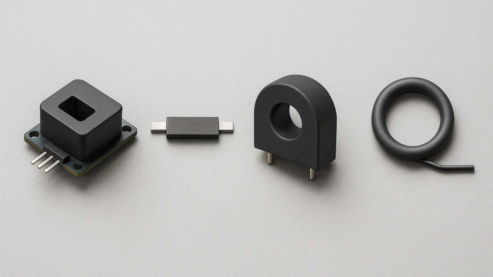
Types of Current Sensors and Their Core Principles
Each type of current sensor makes use of specific physical properties to detect and measure electrical flow. These sensors provide unique benefits for different applications. Modern sensing technologies range from simple resistive techniques to advanced magnetic field detection methods and offer solutions for almost every measurement challenge.
Shunt Resistor Sensors Based on Ohm's Law
Shunt resistors are the most accessible and common current sensing technology. These sensors work on Ohm's Law's basic principle - current flowing through a precision resistor creates a proportional voltage drop. By measuring this voltage, we can determine the current magnitude. Engineers design shunt resistors with very low resistance values to minimize their effect on the original circuit.
Choosing shunt resistors requires careful consideration of resistance value, power rating, and temperature coefficient. Lower resistance helps reduce power loss but makes measurement less sensitive. The resistor must also handle I²R power dissipation without getting too hot. This becomes crucial in high-current applications that generate substantial heat.
To name just one example, see how measurements show a shunt resistor's surface temperature can reach about 80°C under normal conditions. This represents a 55°C rise above ambient temperature. The temperature increase relates directly to the resistor's power dissipation. Double the resistance, and you double the temperature rise. Double the current, and you quadruple it.
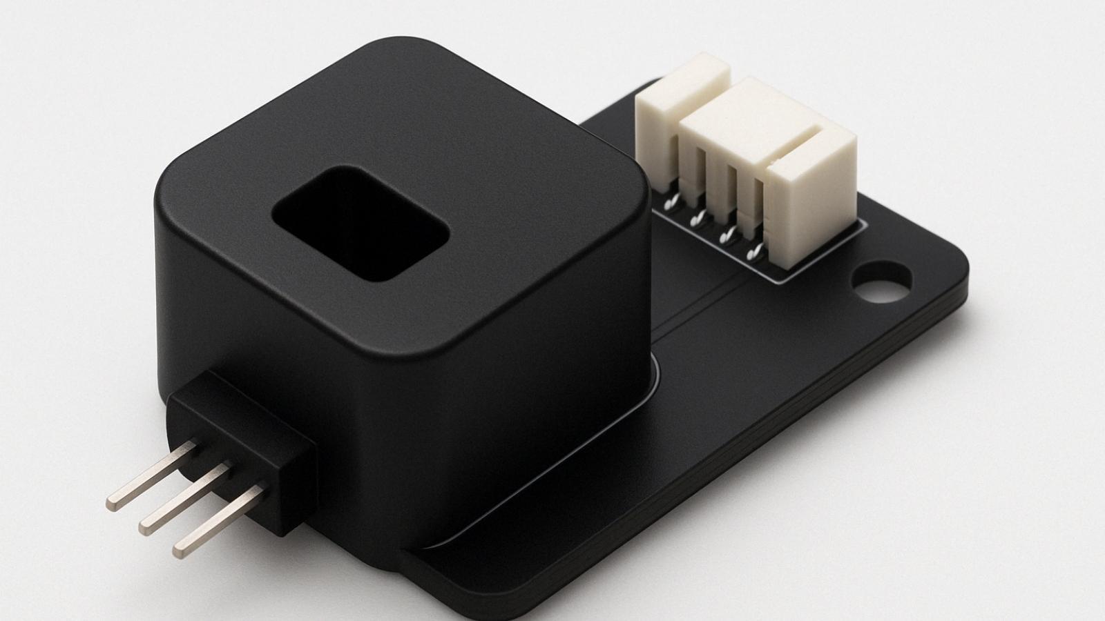
Hall Effect Sensors for Magnetic Field Detection
Hall effect sensors work by measuring the magnetic field that forms around a current-carrying conductor. Current flowing through a conductor creates a magnetic field. This field, when applied across a Hall element, produces a voltage perpendicular to both the current flow and magnetic field direction. The Hall voltage directly relates to the magnetic field strength and thus the measured current.
These sensors come in two main types: open-loop and closed-loop. Open-loop Hall sensors produce output based on magnetic field strength without active control. Closed-loop designs use feedback mechanisms that adjust the output to account for environmental factors like temperature. This design offers better stability and accuracy.
Hall effect sensors create complete separation between the measured circuit and sensing circuit. This makes them perfect for applications where safety and reduced interference matter most.
Rogowski Coil Sensors for High-Frequency AC
Rogowski coils use flexible air-core coils that wrap around the current-carrying conductor. Unlike other options, these sensors detect how fast current changes rather than its absolute value. They excel at measuring quick current changes in AC circuits but can't measure DC currents directly.
A Rogowski sensor has an evenly wound coil on a non-magnetic core. The winding wire returns to where it started through the coil's center. This clever design creates a voltage output that matches the current's rate of change. An integrator connects to the coil to convert this output into a signal that matches the current itself.
Having no magnetic core brings big advantages. The sensor has low inductance, no saturation effects, and responds quickly. The lightweight and flexible design also makes it easier to install in cramped spaces or around large conductors.
Current Transformers for High-Current AC Measurement
Current transformers (CTs) work by reducing high AC currents to lower, measurable levels. They use electromagnetic induction - changing current in a primary winding creates voltage in a secondary winding through varying magnetic flux.
A typical CT has a single-turn primary winding (or "bar primary") carrying the full current and a secondary winding with many turns. The number of primary versus secondary windings sets the output level. CTs provide great accuracy and linearity within their measurement range. This makes them valuable for power generation and transmission.
Fluxgate and Magneto-Resistive Sensors for Precision Sensing
Fluxgate sensors achieve very precise current measurements through magnetic flux modulation. These sensors detect current-created magnetic fields by repeatedly pushing a high-permeability core in and out of magnetic saturation. This B-H loop cycling removes magnetic offset in the core. The result is excellent accuracy with almost no offset.
Fluxgate technology shows much better performance than Hall effect sensors in offset and drift. It offers about 8 μT maximum offset and typical drift of 5 nT/°C. This advantage stands out when measuring small currents where offset effects matter more.
Magneto-resistive sensors include Anisotropic Magneto-Resistance (AMR), Giant Magneto-Resistance (GMR), and Tunneling Magneto-Resistance (TMR) types. Their electrical resistance changes when exposed to magnetic fields. These sensors usually form a bridge configuration to handle thermal drift. This setup provides exceptional sensitivity for precise current measurements.
Materials and Methods: Building a Current Sensor Circuit
Building a functional current sensing circuit requires crucial design decisions that affect measurement accuracy, power efficiency, and system reliability. Your chosen architecture must balance precision needs against real-world constraints like cost, complexity, and heat management.
Low-Side vs High-Side Current Sensor Circuit Design
The current sensing resistor's placement represents a fundamental design choice. In low-side sensing, the shunt resistor connects between the load and ground. High-side sensing positions it between the power supply and load. This placement choice affects circuit behavior and capabilities by a lot.
Low-side sensing gives you several advantages in cost-sensitive applications. The amplifier design becomes simpler because the common-mode voltage stays near ground potential. You can use straightforward single-supply design with ground-referenced output voltage. Low-side configurations let you use simple amplifier circuits and cheaper components.
However, low-side sensing has notable drawbacks. It raises the monitored circuit's ground potential above system ground. This can create ground loop problems that lead to audible noise or equipment interference. The configuration can't detect faults downstream from the shunt resistor, like accidental shorts at the load-ground connection.
High-side sensing puts the load right at ground potential, which removes ground disturbance issues. It can also detect faults occurring downstream from the shunt resistor. These features make high-side sensing ideal for automotive applications and safety-critical systems.
The biggest challenge in high-side sensing comes from amplifier requirements. The amplifier must handle large common-mode voltages and keep high Common Mode Rejection Ratio (CMRR) to stop these signals from appearing at the output. This usually needs specialized amplifier setups that cost more and add complexity.
Using Isolation Amplifiers in Shunt-Based Circuits
Isolation amplifiers separate the measurement circuit from control electronics electrically, especially in high-voltage applications. The selection of an isolation amplifier for current sensing depends on these key factors:
-
Isolation level required: Basic or reinforced protection based on safety requirements
-
High-side power source: Power supply options for the isolated amplifier side
-
Input voltage range: Usually 50mV for high current applications or 250mV for better signal-to-noise ratio in lower current applications
Multi-phase current measurement systems need an isolated amplifier with dedicated high-side power supply for each phase. Very high current applications can use an operational amplifier to boost the input signal and maximize the isolated amplifier's full-scale input range.
The combination of isolation amplifiers and shunt resistors creates a complete solution that gives accurate measurement while keeping safety isolation intact. These systems achieve detection accuracy of ±0.1% and linearity of ±0.1% across their current range. This integration boosts measurement performance in critical applications like motor drives, power converters, and battery management systems.
Signal Conditioning for Hall Effect Sensors
Hall effect sensors need special signal conditioning to work their best. The conditioning circuits remove the offset and offset-drift that Hall elements naturally have while making their small output signals stronger and more usable.
Purpose-built integrated circuits like the DRV411 condition Hall elements in closed-loop current sensor modules. These ICs provide precise excitation circuitry for the Hall element and use special offset canceling techniques that increase the current sensor module's accuracy.
A complete Hall effect signal conditioning circuit has an H-bridge to drive the sensor compensation coil. A 250-mA H-bridge capability can double the current measurement range compared to regular single-ended drive methods. The circuit also uses precision differential amplifiers to create the final output signal with better accuracy.
These conditioning ICs come in thermally enhanced packages that help with heat dissipation. This matters because these components work across temperatures from -40°C to +125°C.
Performance Metrics and Real-World Benchmarks
Choosing the right current sensor means evaluating key performance metrics that affect measurement quality in real-life conditions. Different sensor technologies come with their own strengths and limitations. These characteristics need to match your application requirements to get the best results.
Bandwidth and Frequency Response Across Sensor Types
Bandwidth plays a crucial role in determining how well a current sensor captures rapid current changes. Research shows that a system needs bandwidth at least five times the signal bandwidth to measure a signal with less than 2% error. This becomes especially important when you're measuring switching transients or high-frequency currents.
Each sensor technology responds differently to frequency changes. Shunt resistors shine with their exceptional bandwidth capabilities that reach the MHz range, making them perfect for high-frequency applications. Current transformers also do well at high frequencies and typically work from kHz to MHz. Rogowski coils are great performers in high-frequency AC applications, with bandwidth reaching into the MHz range.
Hall effect sensors work well for both DC and AC measurements but usually operate at lower bandwidths in the kHz range. This becomes a limitation when dealing with rapid current transitions. Recent breakthroughs in tunnel magnetoresistance (TMR) sensor technology have pushed bandwidth beyond 50 MHz. This is a big deal as it means that commercially available chips were limited to just a few megahertz before.
Several factors limit bandwidth, including the sensor's physical principles and its electronics. To cite an instance, see how TMR current sensors can be held back by both the TMR chip and the printed circuit board (PCB) design. The best performance comes from optimizing both components.
Accuracy and Thermal Drift in Practical Environments
Accuracy levels vary greatly among current sensor technologies. Fluxgate sensors deliver exceptional precision between 0.001% to 0.5%, while shunt resistors typically achieve 0.1% to 2% accuracy. Core-less open-loop sensors that use GMR, AMR, or Hall effect technologies are nowhere near as accurate, ranging between 1% and 10%.
Thermal drift presents one of the toughest challenges in real-life current sensing. This measurement in parts per million per Kelvin (ppm/K) shows how much a sensor's output shifts with temperature changes. Fluxgate sensors handle temperature changes well with drift below 50 ppm/K. Hall effect sensors struggle more with drift between 50-1000 ppm/K. This can lead to big measurement errors when temperatures fluctuate.
Temperature compensation techniques help solve these problems. Studies show that proper compensation can bring a sensor's temperature coefficient of sensitivity down to 0.007%/°C. A practical solution uses a compensation sensor with a higher temperature coefficient than the main sensor. This hardware fix works great for commercial sensors where you can't access internal components.
Other environmental factors also affect how well sensors perform. Moisture, vibration, and external magnetic fields can throw off measurement accuracy. Core-less current sensors without good shielding can pick up interference from external magnetic fields. This means you might need extra protection in environments with electromagnetic noise.
Results and Discussion: Matching Sensors to Applications
Choosing the right sensor technology for specific applications needs careful evaluation of operational requirements in different industries. The best sensor choice changes based on current range, accuracy needs, response time, and environmental conditions.
Battery Management Systems and Low-Drift Requirements
Battery management systems (BMS) need current sensors with exceptional precision. These sensors help estimate the State of Charge (SOC) and State of Health (SOH) in electric vehicles and energy storage systems. The measurements affect battery performance, lifespan, and safety. Current sensors serve two purposes in BMS applications—they estimate battery autonomy and detect overcurrent conditions that trigger protective measures.
Low drift characteristics become crucial during a battery's operational life. Small measurement errors add up over time and lead to major SOC calculation mistakes. Fluxgate sensors work great here with drift below 50 ppm/K, making them perfect for high-voltage battery management. When you need very high accuracy, shunt-based technology with isolation amplifiers provides excellent linearity and temperature stability. These typically achieve detection accuracy of ±0.1% across the entire current range.
Motor Drives and Fast Response Time Needs
Motor drive applications need current sensors that respond faster to handle switching transients and enable precise control. A sensor's response time affects motor efficiency, torque control accuracy, and system protection during faults. The sensors must detect overcurrent conditions within microseconds to save expensive power electronics from damage.
To name just one example, see high-performance Hall effect sensors like the MLX91209. They deliver response times as fast as 3μs, making them ideal for inverter applications in electric vehicles. ACS730 sensors are even better with their 210 ns response time and 1 MHz bandwidth. These sensors effectively replace high-frequency current transformers in demanding applications. They excel when you need both high speed and galvanic isolation, like in variable frequency drives and power converters.
Power Grid Monitoring and High Isolation Demands
Power grid monitoring requires current sensors with high voltage isolation capabilities and exceptional accuracy across wide ranges. These sensors must work well despite exposure to substantial electromagnetic interference from nearby equipment.
High-performing sensors come with impressive isolation specifications. MCS18xx series sensors provide 2200V isolation in a single-IC solution. Other sensors achieve isolation ratings up to 1100 Vrms for solar inverter applications. Rogowski coil sensors are great for grid monitoring because they measure a wide range of current analytics precisely. They can track everything from dynamic system loads to fault currents. These sensors quickly respond to changes in current and voltage, including high-frequency harmonics. This quick response enables effective power quality monitoring in distribution grids.
Limitations and Trade-Offs in Sensor Selection
Each sensor technology has its own limitations that need careful evaluation against your application needs. Learning about these constraints helps you pick the right sensor type while dealing with unavoidable trade-offs in performance, cost, and reliability.
Power Loss in Shunt Resistors at High Current
Shunt resistors face power dissipation challenges that get worse with higher currents. Current flowing through the resistor creates power loss based on P = I²R, which generates heat and substantially affects measurement accuracy. This power loss becomes considerable in high-current applications and reduces system efficiency, even with low-resistance shunts.
Temperature rise poses a critical problem with shunt resistors. The resistor's value drifts from its specifications as it heats up and introduces measurement errors. Basic low-cost chip resistors have temperature coefficients around ±500 ppm/°C (0.05%/°C). Specialized current sensing resistors perform better with coefficients between ±100 ppm/°C and ±20 ppm/°C. This thermal drift creates a tough choice - larger resistor values enhance measurement sensitivity but increase power dissipation. Smaller values reduce power loss but compromise measurement precision.
Magnetic Saturation in Current Transformers
Current transformers have core saturation problems, especially when they encounter large currents or DC components. The magnetic core reaches maximum flux density during saturation, which prevents the secondary current from accurately copying the primary current. This nonlinear behavior distorts measurements and can cause protection systems to fail.
High-frequency current transformers (HFCTs) face particular challenges with saturation. Power frequency currents can saturate the core and reduce sensitivity to measured signals. Manufacturers add air gaps to ferrite cores to alleviate these issues. A longer air gap reduces core saturation but decreases measurement sensitivity - creating a direct performance trade-off.
Noise Sensitivity in Open-Loop Hall Sensors
Open-loop Hall effect sensors are highly vulnerable to electromagnetic interference, which creates major measurement challenges. These sensors and their signal conditioning circuits often face conducted EMI problems in AC current-controlled converters. The issues worsen with wide measurement ranges and limited auxiliary power supplies.
Low-cost microcontrollers in digital control systems make noise sensitivity even more obvious. Open-loop Hall sensors show less accurate readings with temperature changes and have sensitivity nonlinearity errors compared to closed-loop designs. Closed-loop configurations eliminate these issues by operating at zero magnetic flux detection points. This removes sensitivity error sources but adds complexity, uses more power, and needs more space.
Conclusion
Selecting the right current sensor needs a balance between performance needs and real-world constraints. A detailed look at current sensing technologies reveals valuable insights about choosing the best sensors for different uses.
Shunt resistors work well as a budget-friendly option for lower current applications. However, power loss becomes an issue at higher currents. Hall effect sensors give great isolation and wide measurement ranges but have some limits in bandwidth and noise sensitivity. Fluxgate sensors shine in precision tasks that need minimal drift. Rogowski coils do their best work in high-frequency AC measurements.
Battery management systems work best with low-drift sensors like fluxgate technology. This ensures accurate state-of-charge calculations as time passes. Motor drive systems need quick response times, which makes Hall effect sensors with microsecond detection a perfect fit. Power grid monitoring needs resilient isolation and wide measurement ranges. Here, Rogowski coils and specialized Hall effect sensors prove most useful.
These technology trade-offs help you pick the right sensors for each case. Every sensor type brings its own strengths - whether you prioritize measurement accuracy, response time, isolation needs, or budget limits. This knowledge equips you to make smart choices when designing current measurement systems for applications of all types.
The success of current measurement depends on how well sensor capabilities match application needs while factoring in environment, measurement ranges, and system limits. This detailed knowledge of current sensor technologies lets you pick and implement the best solution that fits your measurement needs.
FAQs
Q. What are the main types of current sensors?
A. The main types of current sensors include shunt resistors, Hall effect sensors, Rogowski coils, current transformers, and fluxgate sensors. Each type operates on different principles and offers unique advantages for specific applications.
Q. How do I choose the right current sensor for my application?
A. Choosing the right current sensor depends on factors such as the required measurement range, accuracy, response time, and isolation needs. Consider your application's specific requirements, environmental conditions, and budget constraints when selecting a sensor.
Q. What are the advantages of using Hall effect sensors?
A. Hall effect sensors offer complete galvanic isolation, wide measurement ranges, and the ability to measure both AC and DC currents. They are particularly useful in applications requiring high isolation and minimal circuit impact.
Q. How do shunt resistors compare to other current sensing technologies?
A. Shunt resistors are simple and cost-effective for lower current applications. They offer high accuracy and wide bandwidth but introduce power loss and heating issues at higher currents. Other technologies like Hall effect sensors may be preferable for high-current or isolation-critical applications.
Q. What are the key performance metrics to consider when selecting a current sensor?
A. Key performance metrics include accuracy, bandwidth, response time, thermal drift, and isolation capability. Consider the sensor's ability to maintain accuracy across temperature variations, its frequency response for dynamic measurements, and its isolation rating for safety-critical applications.