The breakout board is designed with a 3.3V regulator and level shifting and can be used with any 3V or 5V microcontroller or computer.
This AMG8833 Grid-EYE sensor from Panasonic is an 8x8 array (64 Pixel) of IR thermal sensors. When connected to your microcontroller (or raspberry Pi) it will return an array of 64 individual infrared temperature readings over I2C. The AMG8833 is the next generation of 8x8 thermal IR sensors from Panasonic, and offers higher performance than its predecessor the AMG8831. The sensor only supports I2C, and has a configurable interrupt pin that can fire when any individual pixel goes above or below a threshold that you set.
This part will measure temperatures ranging from 0°C to 80°C (32°F to 176°F) with an accuracy of +- 2.5°C (4.5°F). It can detect a human from a distance of up to 7 meters (23) feet. With a maximum frame rate of 10Hz, It's perfect for creating your own human detector or mini thermal camera. We have code for using this breakout on an Arduino or compatible (the sensor communicates over I2C) or on a Raspberry Pi with Python. On the Pi, with a bit of image processing help from the SciPy python library we were able to interpolate the 8x8 grid and get some pretty nice results.
Board Features
-
Operating Voltage: 3/5V
-
Current Consumption: 4.5 mA
-
8x8 Thermopile Array
-
Temperature Range: 0°C to 80°C (32°F to 176°F)
-
Accuracy Rate: ±2.5°C (±4.5°F)
-
Human Detection Distance: 7m or less (22.966ft)
-
I2C Address: 0x69
-
Dimensions: 30 x 30 mm
Components Required
1 x Evelta AMG8833 IR Thermal Camera 64-Pixel Grid-EYE Breakout
4 x 1 Pin Jumper Wire (Male) - Pack of 10
1 x Breadboard - 830 Holes 54mm x 166mm
Evelta AMG8833 IR Thermal Camera 64-Pixel Grid-EYE Breakout

Board Pinouts
Vin - this is the power pin. Since the sensor uses 3.3V, we have included an onboard voltage regulator that will take 3-5VDC and safely convert it down. To power the board, give it the same power as the logic level of your microcontroller - e.g. for a 5V micro like Arduino, use 5V
3.3V - this is the 3.3V output from the voltage regulator, you can grab up to 100mA from this if you like
GND - common ground for power and logic
SCL - this is the I2C clock pin, connected to your microcontroller's I2C clock line. There is a 10K pullup on this pin and it is level shifted so you can use 3 - 5VDC.
SDA - this is the I2C data pin, connected to your microcontroller's I2C data line. There is a 10K pullup on this pin and it is level shifted so you can use 3 - 5VDC.
INT - this is the interrupt-output pin. It is 3V logic and you can use it to detect when something moves or changes in the sensor vision path.
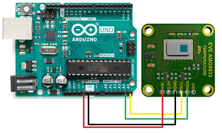
I2C Wiring Connection to Arduino
Pin Connection
-
Connect Vin to the power supply, 3-5V is fine. Use the same voltage that the microcontroller logic is based off of. For most Arduinos, that is 5V.
-
Connect GND to common power/data ground.
-
Connect the SCL pin to the I2C clock SCL pin on your Arduino. On an UNO & '328 based Arduino, this is also known as A5, on a Mega it is also known as digital 21 and on a Leonardo/Micro, digital 3.
-
Connect the SDA pin to the I2C data SDA pin on your Arduino. On an UNO & '328 based Arduino, this is also known as A4, on a Mega it is also known as digital 20 and on a Leonardo/Micro, digital 2.
By default, the I2C address is 0x69.
AMG8833 Sensor Data Read
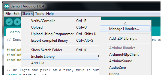
To begin reading sensor data, you will need to install the Adafruit_AMG88xx library.
Start up the IDE and open the Library Manager:
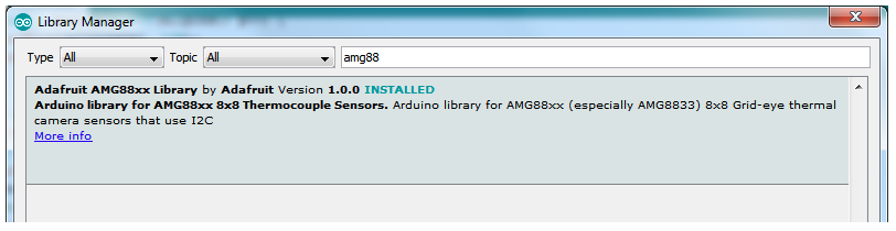
Type in AMG88xx until you see the Adafruit Library pop up. Click Install.
Load Thermistor Test
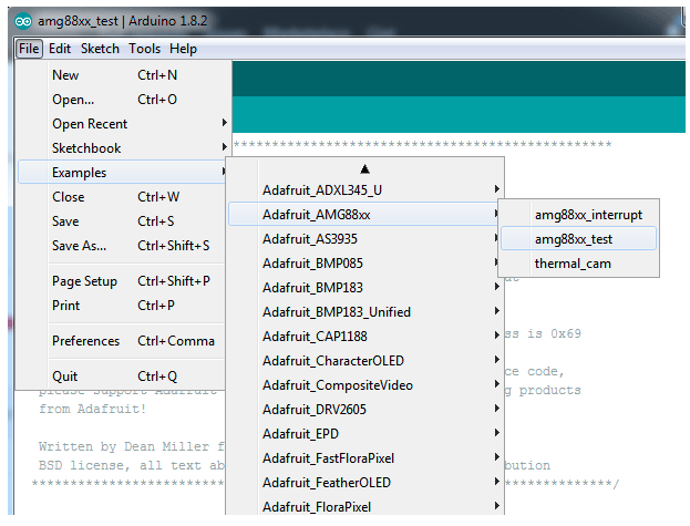
Open up File->Examples->Adafruit_AMG88xx->amg88xx_test and upload to your Arduino wired up to the sensor. This example just connects to the sensor and reads the internal thermistor to test your connections.
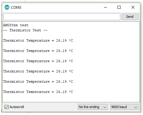
Once uploaded to your Arduino, open up the serial console at 9600 baud speed to see the internal thermistor reading. If you get a reading of ~26° degrees (room temperature) then everything is wired and working correctly.
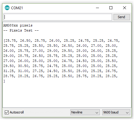
Pixel Array Output
Now that we know the sensor is working, let's read actual thermal data. Load up File -> Examples -> Adafruit_AMG88 -> pixels_test
Upload the code, and open the serial console at 9600 baud rate. You should see a printout of the array of readings every second. Each number is the detected temperature in Celsius, and in the 8x8 grid order that comes from the sensor
The numbers should increase if you put your hand or face above the sensor. They'll decrease if you hold up something cold in front of the sensor eye.