The EVE-ADXL335 is a simple breakout board that allows quick evaluation of the performance of the ADXL335 accelerometer. The ADXL335 is a 3-axis analog-output accelerometer with +-3 g measurement range. The small size 21x16 mm of the breakout board makes it easy to mount the accelerometer to an existing system without the need for additional hardware and with minimal effect on performance of the system and of the accelerometer.
The board measures acceleration with a minimum full-scale range of +-3 g. It can measure the static acceleration of gravity in tilt sensing applications, as well as dynamic acceleration resulting from motion, shock, or vibration.
Key Features
-
3-axis sensing
-
10,000 g shock survival
-
Low power - 350 uA (typical)
-
5V power supply
-
21x16 mm dimensions
Components Required
1 x ADXL335 5V Triple-axis Accelerometer Breakout
5 x 1 Pin Jumper Wire (Male) - Pack of 10
1 x Breadboard - 830 Holes 54mm x 166mm
How MEMS Works
MEMS (micro-electromechanical system) - A MEMS (micro-electromechanical system) is a miniature machine that has both mechanical and electronic components. The sensor consists of a micro-machined structure on a silicon wafer. The structure is suspended by polysilicon springs which allow it to deflect when subject to acceleration in the X, Y and/or Z axis. Deflection causes a change in capacitance between fixed plates and plates attached to the suspended structure. This change in capacitance on each axis is converted to an output voltage proportional to the acceleration on that axis.
Ratiometric output for the ADXL335, that is approximately 0v at -3G to 3.3v at +3G.
EVE-ADXL335 Board

Arduino Wiring Connection
-
Connect the GND pin to GND on the Arduino.
-
Connect the VIN pin to the 5v pin on the Arduino.
-
(For 3.3v microprocessors, connect the pin marked 3Vo to the 3.3v supply)
-
Connect X, Y and Z to the analog pins as shown below

Arduino Code for Testing
constint xaxis = A1; // x-axis of the accelerometer
constint yaxis = A2; // y-axis
constint zaxix = A3; // z-axis
voidsetup()
{
Serial.begin(9600);
}
voidloop()
{
int x = analogRead(xaxis); //read data from x-axis
delay(1); //
int y = analogRead(yaxis); //read data from y-axis
delay(1);
int z = analogRead(zaxix); //read data from z-axis
float zero_G = 512.0; //ADC is 0~1023 the zero g output equal to Vs/2
float scale = 102.3; //ADXL335 Sensitivity is 330mv/g
//330 * 1024/3.3/1000
Serial.print(((float)x - 331.5)/65*9.8); //print x value on serial monitor
Serial.print("\t");
Serial.print(((float)y - 329.5)/68.5*9.8); //print y value on serial monitor
Serial.print("\t");
Serial.print(((float)z - 340)/68*9.8); //print z value on serial monitor
Serial.print("\n");
delay(1000); //wait for 1 second
}
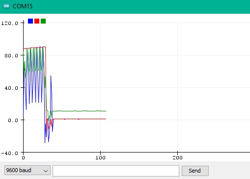
Output
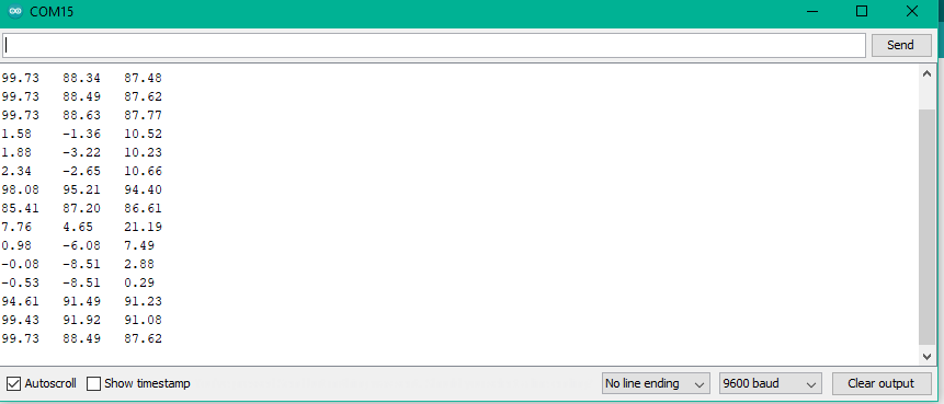
Graph Plotter